This is a patch panel. Sort of looks like an old telephone operator’s plug board. Each vertical line of holes, 5 each, are wired to one dimmer.

Here we can see all the circuits waiting to be used. These wires are connected to the circuits in the electric pipes.

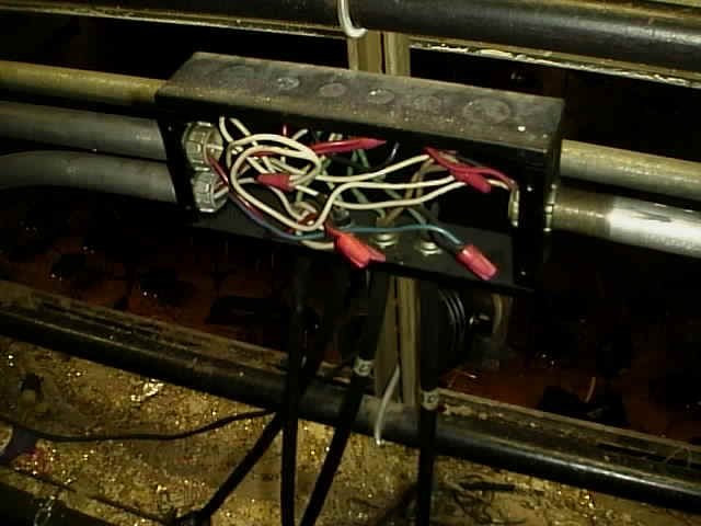
Can you say code violation? This box should be covered. ON the left we see conduit coming into the junction box. Hanging from the bottom are four circuits.

Electrical Network
From Wikipedia, the free encyclopedia.
An electrical network or electrical circuit is an interconnection of analog electrical elements such as resistors, inductors, capacitors, diodes, switches and transistors. It can be as small as an integrated circuit on a silicon chip, or as large as an electricity distribution network.
A circuit is a network that has a closed loop i.e. a return path. A network is a connection of 2 or more simple circuit elements, and may not be a circuit.
The goal when designing electrical networks for signal processing is to apply a predefined operation on potential differences (measured in volts) or currents (measured in amperes). Typical functions for these electrical networks are amplification, oscillation and analog linear algorithmic operations such as addition, subtraction, multiplication, division, differentiation and integration.
In the case of power distribution networks, engineers design the circuit to transport the energy as efficiently as possible while at the same time taking into account economic factors, network safety and redundancy. These networks use components such as power lines, cables, circuit breakers, switches and transformers.
To design any electrical circuits, electrical engineers need to be able to predict the voltages and currents in the circuit. Linear circuits can be analysed to a certain extent by hand because complex number theory gives engineers the ability to treat all linear elements using a single mathematical representation.
A number of electrical laws apply to all electrical networks. These include:
- Kirchhoff’s current law: the sum of all currents entering a node is equal to the sum of all currents leaving the node.
- Kirchhoff’s voltage law: the directed sum of the electrical potential differences around a circuit must be zero.
- Ohm’s law: the voltage across a resistor is the product of its resistance and the current flowing through it.


Recent Comments